Click on any image to enlarge it; click again to restore.
For maximum resolution, right-click on an image and choose "Open image in new tab".
This gizmo was mounted on the wooden stairway wall in the basement of my circa-1890 house in Connecticut. It was here when we bought the house in 1986. The photo below shows it on the wall but without its cover. The rest of the pictures show the gizmo on my workbench.
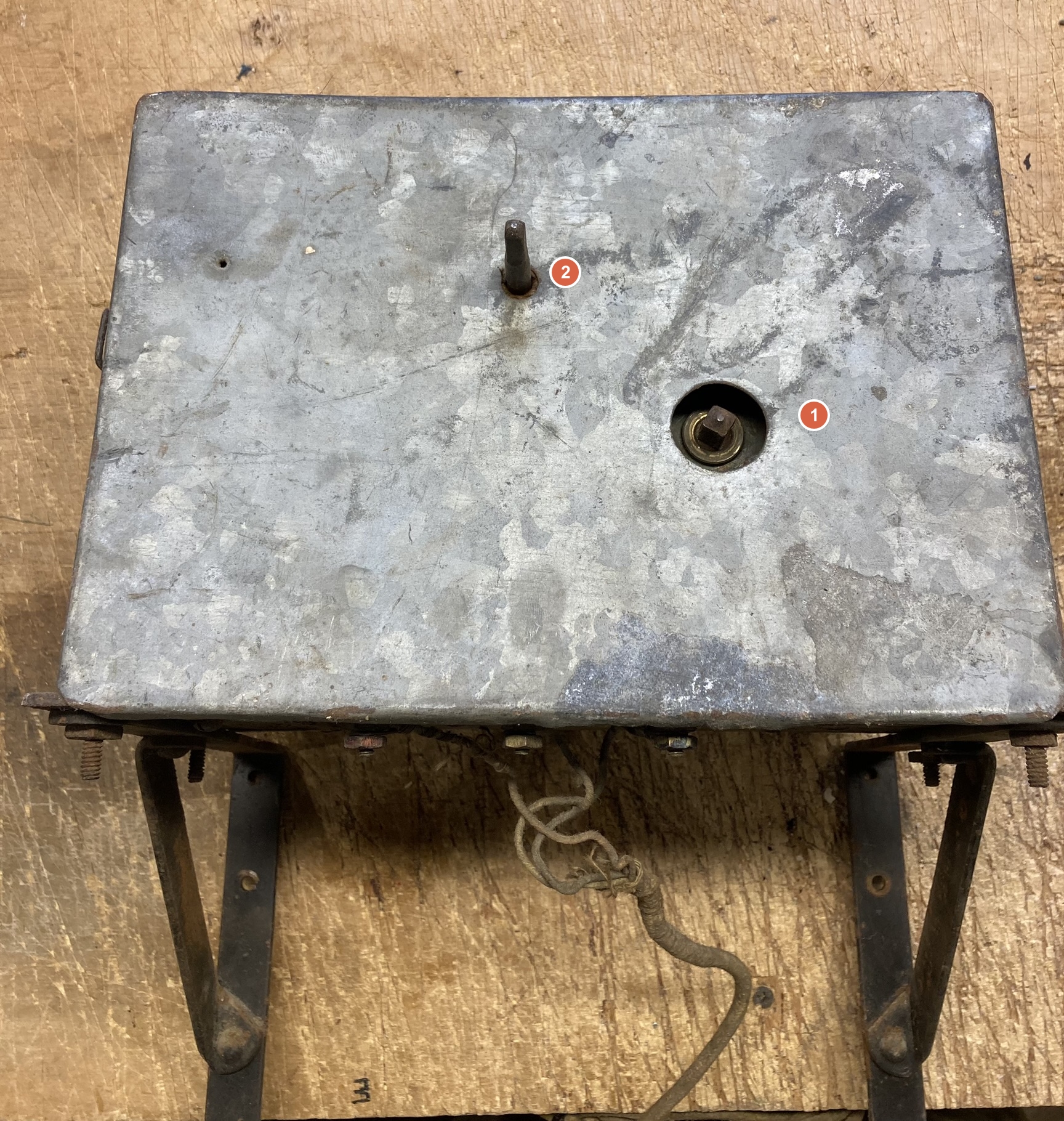
It's about 10" wide x 6" tall x 5" deep. The front cover exposes (1) a shaft used to wind up a big spring, and (2) a shaft that turns very slowly when the mechanism is running.
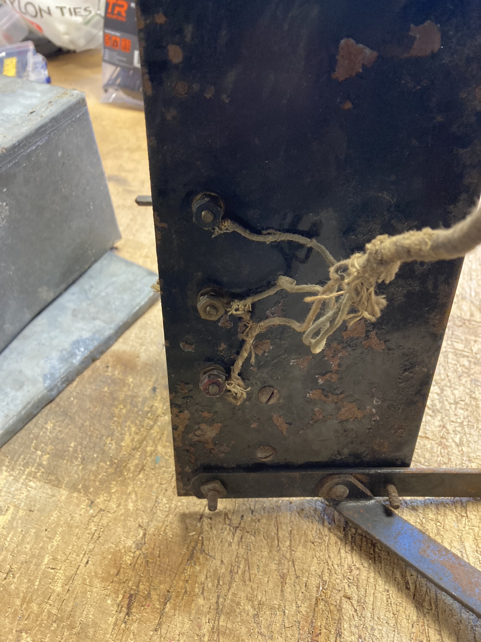
The bottom. A 3-conductor wire enters at the bottom.
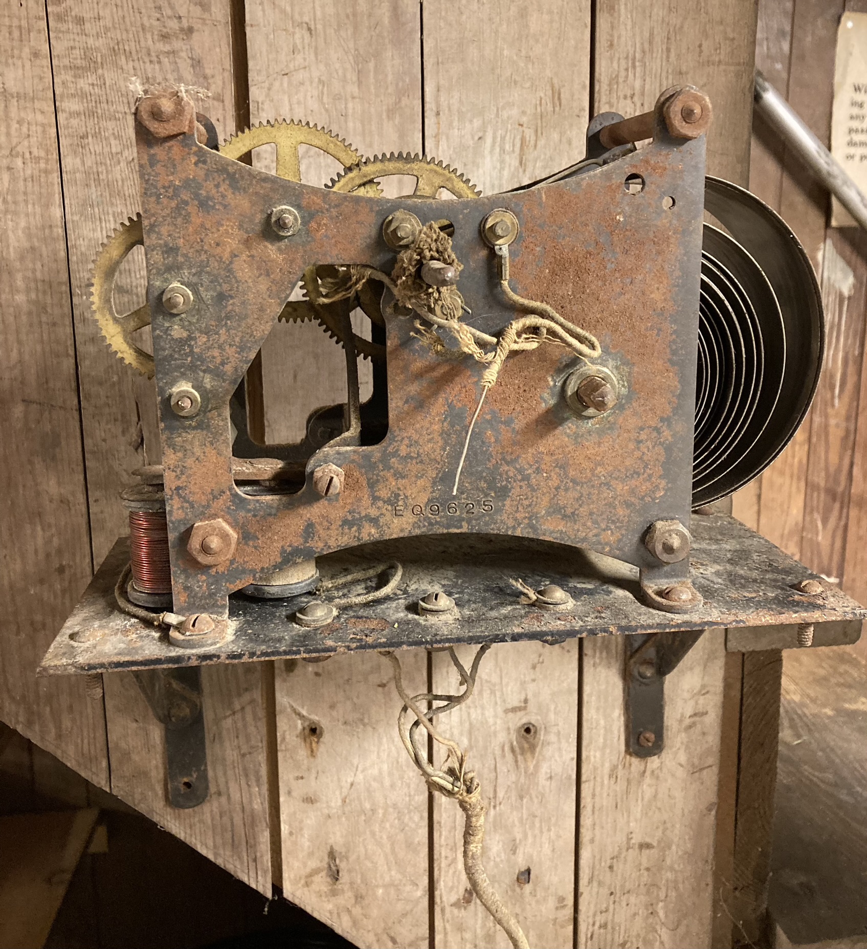
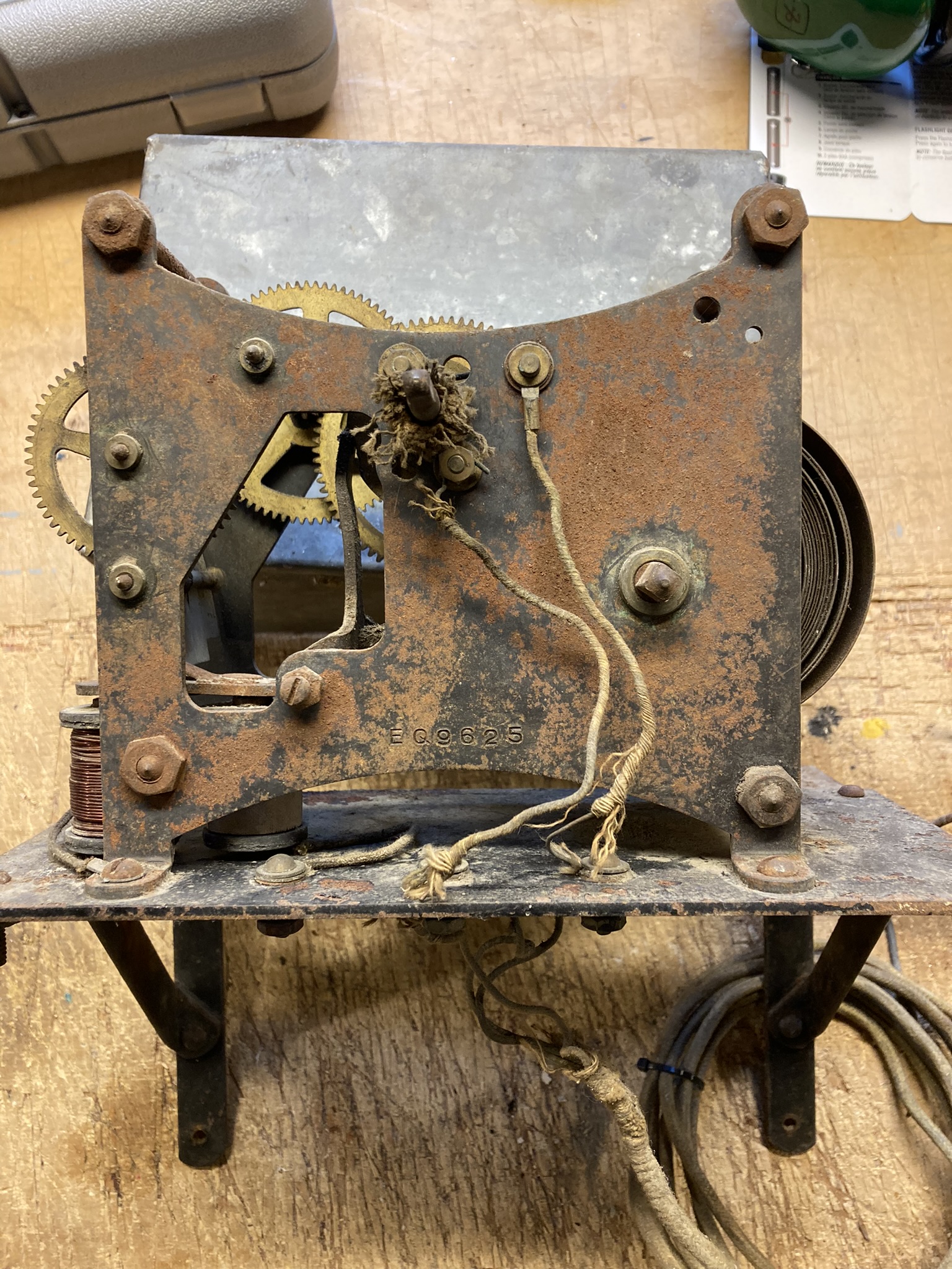
This is the front with the cover removed. Note the big spring on the right and the gear mechanism on the left. There is also what looks like a serial number: EQ9625.
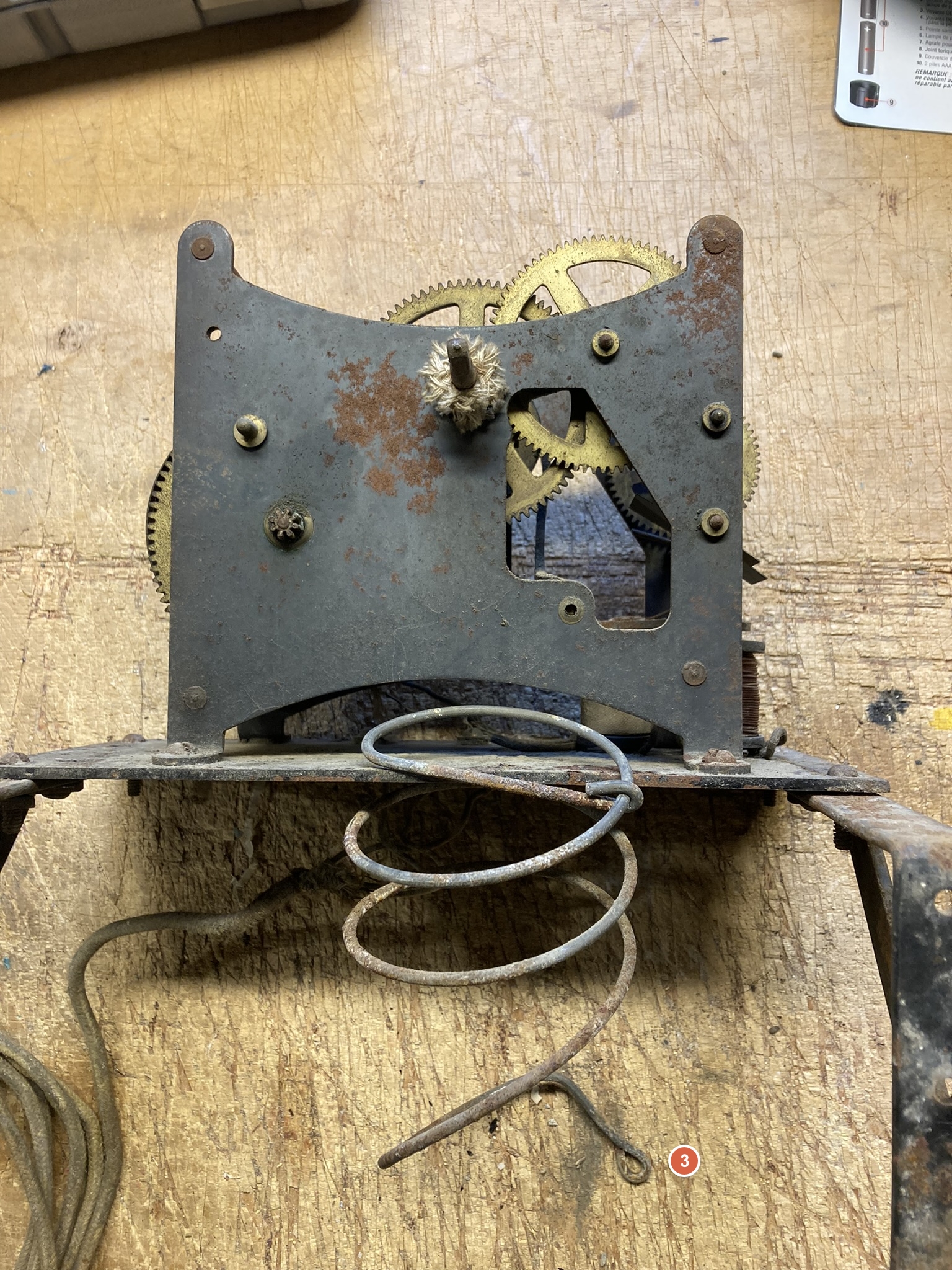
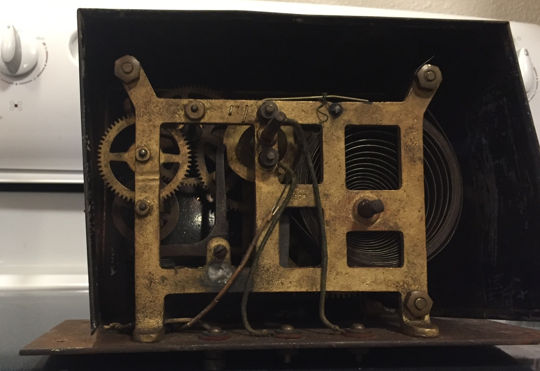
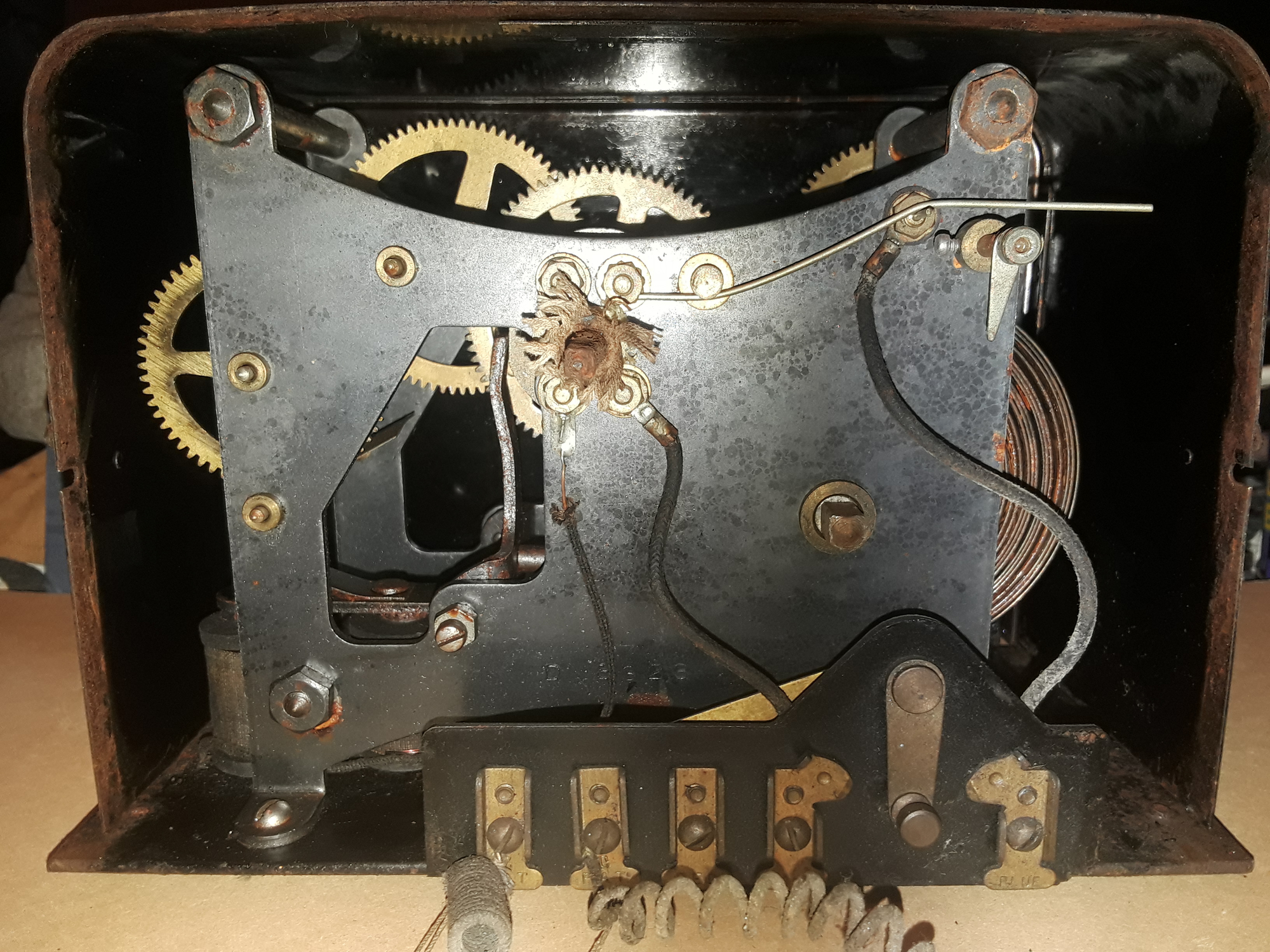
This is the back with the cover removed. Note the large coiled wire below. The little loop (3) was screwed into the wooden stairway wall just below the gizmo. It is not clear to me if the top was attached to the device, but its location strongly suggests that it was.
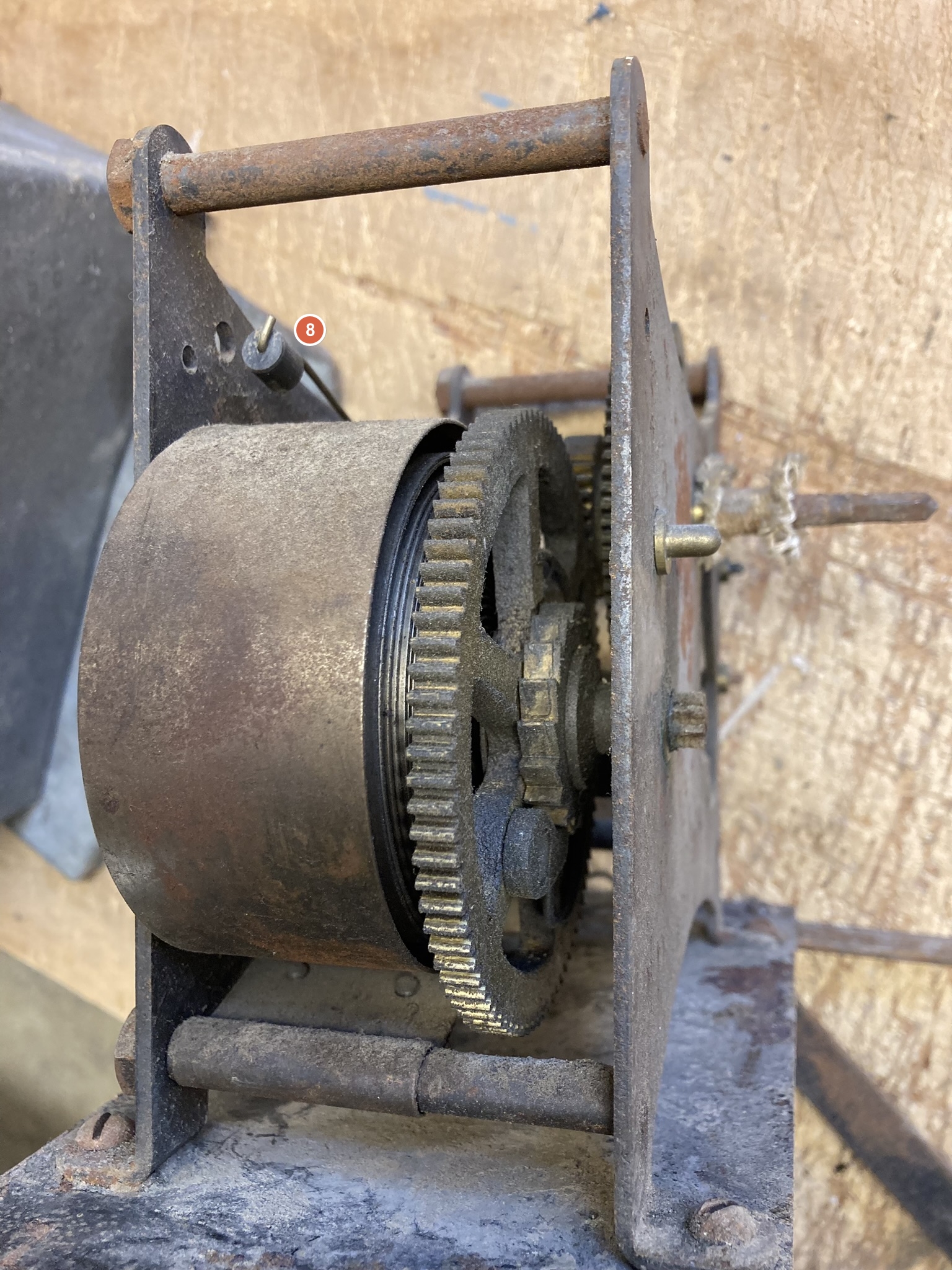
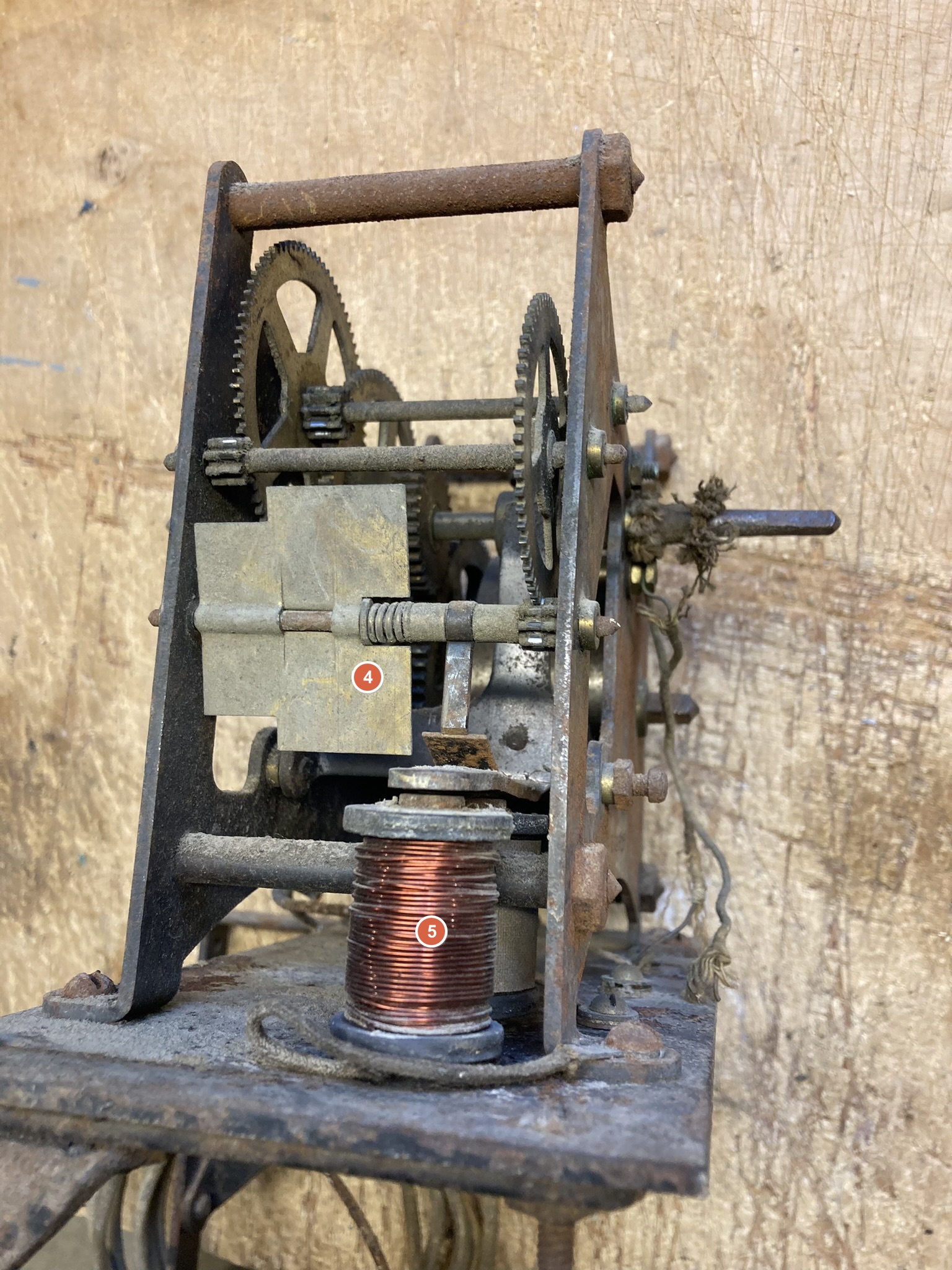
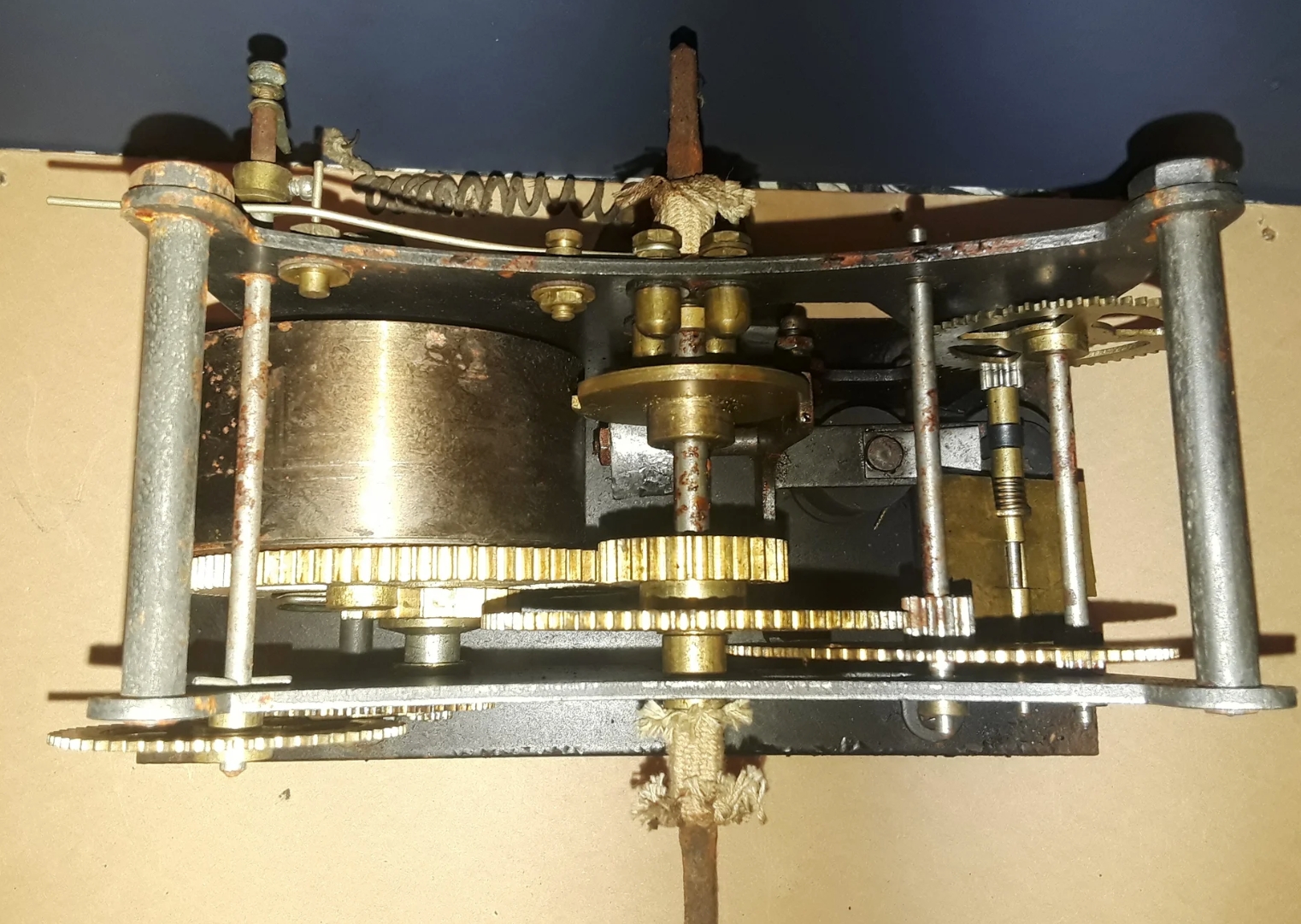
This is the left side. When the mechanism is running, the gears turn and the paddles (4) spin rapidly. The copper coil (5) looks like a magnet which would start and stop the mechanism. There is another spool-shaped device behind (5). It has been suggested that the paddles act as a speed governor. Or perhaps they are to cool the magnet?
A closer view of the left side. When the magnet is not on, a gap (6) is created as the lever above it rises. A piece of metal (7) catches the spinning paddles and stops the mechanism as you see here. When the magnet is activated, the lever just above it is pulled down, the gap closes and the paddles are released, starting the mechanism. (I have not activated the magnet, but I can simulate this by hand.)

The right side, showing the main spring. The thingy that looks like a bell striker (8) is fixed in position, I think just to limit the expansion of the main spring as it unwinds.
There was an old chimney a few feet away from the gizmo. Based solely on that, I speculate that this was a "remote control" for a coal burning stove in the basement, and the gizmo had something to do with feeding coal into the stove.
(A friend suggested that if this was the case, I may have the first Smart Home!)
Another friend asked: Why use a wind-up clockwork mechanism if electricity was available? I'm guessing that it might have been powered by a battery which was strong enough to power a magnet to start and stop the mechanism, but not strong enough to run a motor.
Anybody have a more educated guess...?
Rex Swain
Washington, CT
Tel 860-868-0131
rex@rexswain.com
I was on the right track, but the actual purpose of the device was to control the damper of a coal stove. Here's some history...
In 1885 the inventor Albert Butz in Minneapolis patented a furnace regulator and alarm. His company eventually became Honeywell (see Honeywell Company History).
From the Hennepin History Museum, The Invention of the Damper Flapper and the Birth of Honeywell:
I gather that the most innovative part of the system was using a thermometer to create an action: a thermostat, which would make Honeywell a household name.The damper flapper was a system that controlled coal fire furnaces. When the temperature inside a home became too cold, Butz's invention would lift the damper on the furnace, allowing air to fan the flames, thus automatically increasing the temperature of the residence. The device was composed of three components, a thermostat, a battery, and a motor.
My gizmo was an early version of the "motor", using a wind-up clock-like mechanism before electric motors were readily available. (Subsequent versions of damper flappers would use electric motors.)
From a post on HeatingHelp.com in 2017 by Ed Harrison The electric heat regulator company damper flapper, and thermostats:
About 20 years ago while working on a boiler in Seattle, I found a old control on the wall that consisted of a copper spring, brass gears, and some wiring. Of course it had been long ago disconnected, and somehow I was able to convince the owners of the house to give it to me. Through some recent research, I was able to find out that it is what was called a damper flapper, manufactured by the electric heat regulator company, and when connected to a thermostat and battery, would open or close the damper of a coal furnace or boiler.
Note that his is very similar but not the same as my gizmo. His is stamped with the year 1906.
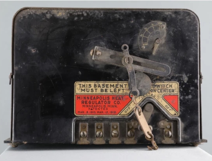
HeatingHelp also had a couple of pictures posted by "katie86myers" of another model that is almost identical to mine:
When the device was activated, the drive shaft would turn one-half turn and then stop.
In the picture below of a later electric damper flapper, you can see how half a turn could be used to raise and lower something like a damper. Apparently a system of chains and pulleys was sometimes used.
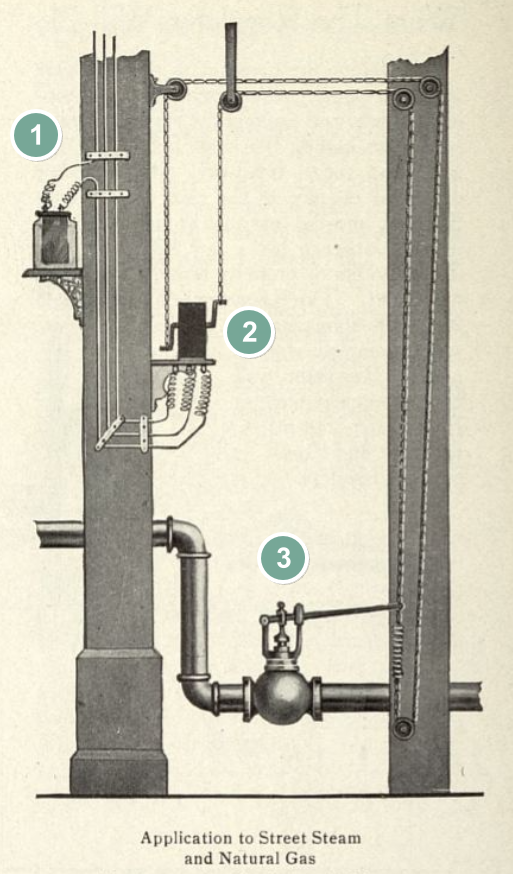
And in the picture below (from the Minnesota Digital Library) you can see another example although using a different kind of valve. (1) is the thermostat, (2) is the gizmo, and (3) is the valve.
That's all, folks. Thanks to everyone who contributed.
Last updated 15 February 2023
You are visitor
since 14 February 2023
Rex Swain, E-mail rex@rexswain.com, Web www.rexswain.com